Friday, February 29, 2008

Artefact Four - 3DS Max Renderings and Composition (Part 1)

The last two artefacts have been dealing with light in a space and how light reacts from objects, this forth artefact will bring the final step to these renders. Adobe Photoshop will be used to create a composition of a render to give further depth by giving the shaded/lit areas a more dominant outcome in the final image for a scene. The artefact will be investigating how this is done and also how it differs from a render from 3DS Max.

Why Composition?
This technique is used everywhere in media today from multi-million dollor films to simple weather reports, the technique is to use images stacked uppon each other to create a new image. In this case for the experiment rendered images from 3DS Max will be placed into Photoshop to adjust the elements of the image and create a improved level of realism to the final output. This is not to say this method is indefinately better than what 3DS Max can produce but simply a further step in production to assess if this method is worth while.

To create the composition in Photoshop the first step was to get the rendered images. A list of renders can be made from the same scene in one go by selecting Rendering>Render Elements tab.

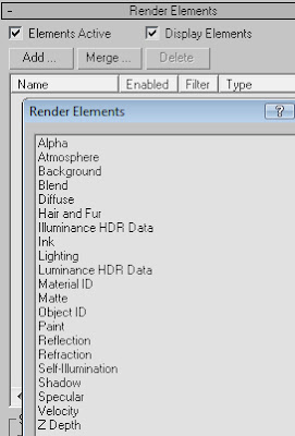
From the Render Elements tab, clicking on add will allow a user to create multiple renders and these will change how the final composition will look. For the first experiment only a couple renders will be used. Only the diffuse render was selected this will give the colour needed for the scene and a seperate render that uses Occlusion will be used for the shaded areas described later.

Original render dark scene created in 3DS Max using Mental Ray. Mental ray was chosen as it has given better looking renders from the results of artefacts two and three.
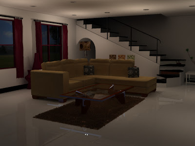
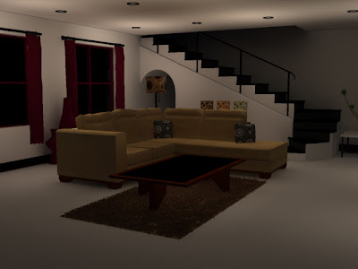
Diffuse Render

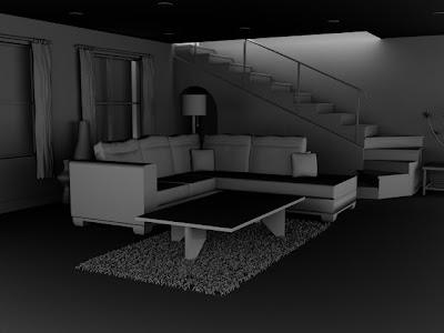
Ambient Occlusion Render

The resulting effect that the Occlusion render will give to the final composition are softer looking shadows, this is calculated from the ambient light in the scene – independent from the original light source. This greyscale occlusion will allow the shaded areas of the initial render to have more depth from the original Mental Ray render.
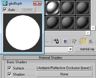
To create this render and make this “Clay effect” all objects need to have the same map applied to them. Using a Mental Ray map the surface section on the Basic shaders area needs to use an Ambient/Reflective Occlusion sub map. To finally allow the render to give the clay look the ‘Global Ray Antialiaser’ needs to be on and the map created must be placed here. The resulted procedures can be seen below in the render.
At times the initial render for the Occlusion output creates a bad image where grain is can be seen creating an image where noise has been engineered. This must be discarded now before using the image later in the final composition.
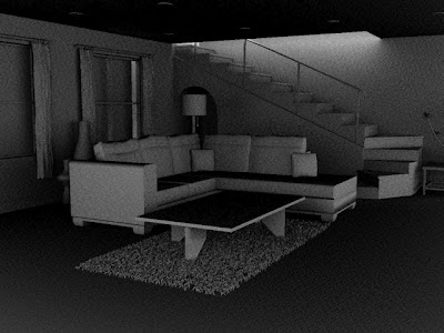
To make the grain dissipate from view the sample per pixel quality needs to be increased. This basically increases the amount of information per pixel giving a smoother look to the render. However the larger the samples rate the longer the render time. The original setting is set at ¼ and after test renders the best output with minimal time consumed was setting both minimum and maximum ranges to 64 samples per pixel.
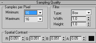
Below shows how the Photoshop layers have been setup and what has been attached to them e.g. the exposure for the living room dark layer. The ambient occlusion layer has been inverted to allow the image to become brighter in the final output.

The diffuse map will give colour to the scene whilst the initial Mental ray render will show all the reflections of the shiny surfaces such as the floor and the glass table top. The specular map was used to give added highlights and bring out the well lit areas of the scene however the rendering was too dark so it was discarded. Finally the ambient occlusion map was placed on top of the stack.
Below is the final composition, the image on the left was the initial render from 3DS Max and the image on the right is the newly created composition. I believe that the rendered image is still better, the shaded areas where the light struggles to reach is more dominant than the composition. Thus giving the image the depth that gives the room distance whilst looking at the composition image the whole thing looks a bit flatter.
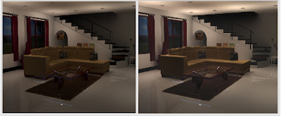

The final outcome of the composition was slightly disappointing the main reason being that the specular map was too dark to use which is why the scene still looks too dark and the depth is not quite there. After browsing the Web (mainly 3D forums) I have gained the knowledge that in 3DS Max there is a problem with using Render Elements alongside the Mental Ray renderer. The Scanline renderer is the optimum partner for rendering elements. The scene lights will be recreated and a composition will be tested again with the new Scanline renders.

Artefact Four - 3DS Max Renderings and Composition (Part 2)

After re-lighting the scene the Scanline rendering system indeed worked on all of the render elements that will be used for composition in Photoshop. This time round adding to the amount of renders by including; shadow, lighting, a re-render of the scene using Mental Ray, and a specular render. Below is the resulted imagery.

Below are the images stacked in Photoshop, the easiest way to adjust the images is to turn half of them off and work with the second, then vice versa. Once the stack has been complete then any final adjustments can be made.

Below is a step by step account with jpg images to show what adjustments was used to create the final composition The shadow image was first set to multiply, thus making the image very dark to begin with. However once this is set the lighting in the scene can then be added and thus will bring out the colour so objects can be recognised.


The specular image was then included and was set to screen. This allowed the colour of the scene to be identified, note that this makes the shadows look quite dominant for the moment. In the real world shadows have gradients and not always pure black.


To soften the shadows to create this gradient look a linear burn was introduced to swap the initial multiply. Giving a nicer feel to the shadows. Notice that the couch and curtains now have also been brought out.


To enhance the shaded areas further (but not making them totally transparent) the lighting render was then issued a soft light blending mode. However this should be done carefully to simulate the distance of a light, for example it is not needed if a light is fairly close to an object as the shadow created would be quite dark. At this instance the other rendered layers were not need in this composition as they did not enhance any of the image when they were brought in so were rightfully not used. Below lays the final composition of the living room.

The final task of this artefact was to ask an audience of their opinions of which image like the best out of;
  • The composition
  • The Mental Ray Rendering
  • The Scanline Rendering.
Below is a reminder of the two initial renderings.

Initial Mental Ray Rendering
Initial Scanline Rendering

A pie chart to show the number of people that preferred which final image.


The results can be seen that an incredible 0 people preferred the Initial Scanline image whilst twice as many preferred the newly created composition. The comments made are also useful to have so this can be adapted in a future project. Many people who preferred the mental ray image liked the look of the rug and a lot said that the shaded areas are more realistic due to the softness of them. However this can be easily amended in the composition by reducing the shadow amount and altering the light to compose the shaded areas. Most of the people who preferred commented on the shadow cast by the table in the centre, due to the table surface having a glass material the light passes through this but does not with the wooden frame.

Evaluation
In the last two artefacts Mental Ray has been undoubtedly come across as the best output for renders. For this artefact pure mental ray renders did not perform as the software would not enable the output needed for making a composition in Adobe Photoshop. However combining Mental Ray and Scanline renders, one can create output that perhaps not outright better 3DS MAX renders but enables the user to create adjustments easily and quickly for specific output. Using the render elements area of Max a user can chose what renders to use for the composition. Whilst using the default Scanline Renderer the output takes far less time to be created than using Mental Ray. But once again the benefit of creating a composition of these renders is the fact that they can be easily amended. For example if a shaded area needs to be darker, or the diffuse colour needs to be higher in contrast they can be altered in Photoshop using the layers that were created with the 3DS Max renders.

Conclusion
Using software to create post rendered images can be a benefit to the outcome of a render, to take this further software’s such as Shader, Zbrush and Photoshop can be used not just to enable a more realistic outcome but can also be taken further to create imagery for film or games. For example something as simple as changing the lighting effect could dramatically alter a composition to create covers for DVD’s or posters for different Medias and genres.

Friday, February 22, 2008

Artefact Three - Object Lighting (Part 5)

Photon Mapping

3DSmax uses photon mapping when calculating caustics. This procedure allows max to trace rays from a light source until it hits an objects surface, it is then given a luminance value (a calculated amount of light that either passes through or emits from a surface). It is used to realistically simulate the interaction of light with objects. Photon mapping takes most of the time when rendering a scene, it calculates then simulates
A cheap way of creating caustics is max is by using a coloured shadow and a falloff map that creates the transparency that a glass objects possess. Thus the light that is refracted from it can be combined to create this ‘fake’ caustic effect. A scene made in 3DS Max was created with a glass cylinder in a room. Firstly the glass material has been given a blue diffuse colour (this could be any colour) so that later on the caustic effect can be seen over the blue colour.


Raytrace has been used for the refraction map, this gives the cylinder the transparency to make it look like a glass material.


Placing a spotlight into the scene directed at the glass object if the scene was rendered now it would not have a shadow because ‘shadow maps’ is currently assigned to the spotlight and they ignore transparency which is not what is needed when creating caustics. For this ‘raytrace shadows’ needs t be assigned to the spot light.
Below is the rendered scene, notice that the shadow is blue due to the shadow parameters of the light have been changed to blue. Otherwise it would be standard black/dull grey.


Now to create the fake caustic another light needs be placed into the scene and should be placed near the previous light. Below is where the light created has been placed.


The first light created has a blue shadow colour parameter – this to follow the colour that the glass tint has. The new light however needs a white colour shadow – this follows the normal caustic colour of white light. The other parameter that has been changed is the shadow density to a larger one. If left as the previous, the caustic effect will scatter to the whole refracted area and nothing would be seen. The resulted changes can be seen in the rendered scene below.


Notice that the density has been altered to a higher 2.5. The larger the density the stronger the white coloured caustic will be. However to overpowering will result in an unreal look as the white light would seem to pass straight through the glass cylinder and not been refracted at all!


The shadow density of the second (caustic making) light has been set to 10, this looks unrealistic as it does not look like the light has been refracted but has just simply passed through the cylinder.
Here, more objects with the same glass properties have been placed into the scene to see how the caustic simulation reacts to the differentiating shapes.


Finally to see how this fake caustic effect measures up to the previous experiment, the glass used previously will be placed into this scene. Below is the outcome of the experiment. Note that the light colour and the material colour has been issued a white colour to make the material look as close as possible to the previous experiment.


Evaluation
In 3DS Max the standard default renderer (Scanline Renderer) allows a scene various methods for simulating reflections and refractions. The most accurate methods are usually the most expensive time wise. In max the user controls the amount of highlights on a material using the specular controls such as glossiness and the amount of shine. Alongside this the material can also have a reflection map added to it, allowing the environment around the material to be reflected onto it from a light source. Using a raytrace material I found out that this method produces most accurate results, granted that the rendering time is partially slower the resulted renders output come out well. The output given does not always necessarily need to be accurate, for example the reflected light on the pool ball experiment and the results given suggest that real world simulation can be faked with 3DS max to achieve the same outcome. Not only does this save on render time and patience but also how people perceive or take for granted how light works on a simple surface. Compared with real world lighting we generally refer an objects specular characteristic as a simple reflection from a light source. The Scanline Renderers lighting is global and this means that this infinite light illuminates objects from every point. Real world lights however do not do this, the light comes from a source point such as a bulb and this can be adapted well in Max by using various lights such as spot or Omni lights.

Conclusion
Mental has certainly been experimented with in the past two artefacts on various tests, it does seem that this rendering system is of a higher standard than the default Scanline renderer. It can be seen why it is used in the industry today, and gives excellent results especially for realistic output. Another rendering system that is also used in the industry is Vray, a more costly option in terms of price I shall investigate what sort of output this creates as well as why this differs (if it does) to the mental ray.
Artefact Three - Object Lighting (Part 4)

CAUSTICS

Caustics are produced by rays of light that are reflected or refracted by a curved surface or an object, or the projection of that envelop of rays on another surface. (Wikipedia Caustic - Optics). The example to show this below is a glass with some wine stored inside. Note that the light present in the room casts a shadow of the glass onto the surfaces behind it. There are also bright streaks of light that pierces the shadow and these are the caustics created from the glass and wine.


The next stage of the artefact is to assess how to create caustics within 3DS Max, the reason being that it can be used in my future projects so that my scenes can follow real world lighting. After reading extracts from ‘Rendering with Mental Ray & 3DS Max’ by Joep Van Der Steen, the best way to create caustics is to use the Mental Ray rendering engine. The reason being is that it calculates distributed photons, global illumination and this analyses where caustics should be projected.


The scene that I will be creating to experiment with caustics will be a glass on a plane. The glass material for the glass will simply be a Raytrace material on the refraction map (for photon mapping).


The object properties are vital for caustics. The user must assign what object will generate caustics (the glass) and what object will receive them (the table). To find these settings, the object should be right clicked – object properties – mental ray. From here the appropriate checkbox should be enabled or disabled.


The image below shows where the objects and lights have been placed for the scene.


The final amendment that is needed for the scene before caustics can be created are the settings in the rendering setup. As the mental ray renderer has been enabled there is a ‘Caustic and Global Illumination’ area in the ‘Indirect Illumination’ tab. This is where it all happens. Enabling caustics here will then render them in the scene.


Below is the rendered scene. Note that the light has cast a shadow of the glass onto the plane and the bright caustic areas have also been projected.


The next stage was to enable global illumination (the check box in the rendering setup). This intensified the caustic areas and some scattering has also occurred.


A simple box has been placed behind to see what effect this would have on the caustic projected from the glass. We know that in the real world that shadows will hit an object like it does in this scene. We can also see that the caustic follows this pattern of the shadow, however it can be seen that the caustic has intensified on the box.


The next part was to see how changing parts of the scene can affect caustics. The first change that was tried was to add some liquid into the glass. Below you can see the glass is just over half full and the caustic has been altered to a specific area to the far right of the picture. Also the light has also reflected back toward where the light source has come from, to the left of the picture there is a small arc of light that can be seen.


The next change was to alter the light source, throughout the experiment so far the light source has been an Omni light. The amended light has been placed in the same area as the previous lighting to remain consistent.


The image above on the top has a spotlight light source facing the glass. The caustic has spread out and is dotted to the right of the scene. The image on the bottom has a skylight and the only caustic is the reflected one to the left of the image however it has increased in size from the Omni light earlier in the experiment.

My final change to this scene is to see how caustics are affected by using a different shaped glass. Using a more traditional shaped wineglass the image below is of the newly rendered scene. Note : the lighting was exchanged back to the original Omni setup.


Artefact Three - Object Lighting (Part 3)

As the image above shows the metal reflects the surrounding area, in max this can be done by using a reflective map and issuing an image that will be seen on the metal surface. The bonus of this is that the user does not have to make another object that holds the map information of the image that needs to be seen in the reflection. Below is the reflected bitmap parameters. The image that shall be used initially is a kitchen scene (below).


As the image above shows the metal reflects the surrounding area, in max this can be done by using a reflective map and issuing an image that will be seen on the metal surface. The bonus of this is that the user does not have to make another object that holds the map information of the image that needs to be seen in the reflection. Below is the reflected bitmap parameters. The image that shall be used initially is a kitchen scene (below).


A way of choosing the dullness and reducing the reflections intensity of the kettle in the scene is to change the RGB amount. This is quite important especially if a HDRI image will be used to create the reflected scene. As unlike a JPG image (above) a HDRI image value has a greater RGB value, not only does it store the images coloured pixels but also the intensity of light within each pixel also.

RGB set at 0.1

RGB set at 0.5

RGB set at 1

RGB set at 1.5


By changing the reflective maps RGB amount a user can easily acquire in effect a luminosity of the room without affecting the lights. The higher the RGB amount the more and intense the reflection amounts to. The final render is with a HDRI reflection map, note (below) that the map is a circular and has its own illumination present.


HDRI (High Dynamic Range Image)

The final render of the kettle below. It seems to have the same characteristics as the image of the pot, the colour is present the reflection is projected around the surface and is distorting the further away it gets from the user.